




































Scope
APA designed an underground reinforced concrete (RCC) valve pit accommodating a 48″ pipeline, a centrally located Motor Operated Valve (MOV), two 10-inch branch connections on independent pipe supports, and a steel access platform. Structural components included the RCC base slab, RCC retaining walls, a valve support pedestal, pipe support pedestals, and a structural steel access platform with chequered plate flooring.
The structure was designed to safely resist concentrated valve loads, pipeline dead and fluid-filled operating loads, maintenance loads, earth pressure, surcharge, groundwater uplift, and long-term settlement — with an integrated load-transfer path linking the valve pedestal, pipe support pedestals, access platform, retaining walls, and common foundation slab, while maintaining required pipeline alignment and clearances.
Design standards: ACI 318-19, ACI 350-20, AISC 360-22, and ASCE 7-22. Analysis and steel member design performed in STAAD.Pro.
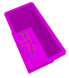
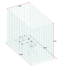
3D Pit Model View & Dimensions
Design Verification
- ● Flexural, shear, and bearing pressure design of the RCC base slab and retaining walls (500 mm thick)
- ● Uplift and sliding stability, and settlement assessment of the supporting foundation
- ● Punching shear evaluation and reinforcement detailing for the valve support pedestal
- ● Structural steel column and beam design for the pipe support pedestals, including base plate and anchor bolt connections
- ● Access platform beam design for deflection, vibration, and member utilization ratio per AISC 360
- ● Connection design — beam-to-support, base plate & anchor bolts, bolt shear/tension, and weld strength
- ● Crack-width control per ACI 350
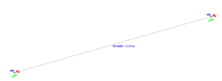
Chequered Plate Supporting Steel Beam
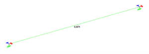
Member Property & Dimension Utility Ratio
Key Engineering Challenges & Design Solutions
1. Clash Detection
Challenge
Avoiding clashes between pipe supports, the valve support, platform beams, and pit walls.
Solution
Performed detailed 3D model reviews and clash detection between supports and beams, resolving clashes by adjusting member sizes and locations.
Outcome
Achieved a clash-free, constructible 3D model — improving installation feasibility and reducing site modifications and rework.
2. Integrated Foundation Design & Settlement Control
Challenge
The base slab had to act as a common foundation for three separate pedestal types (valve, pipe, and platform) while resisting continuous lateral earth pressure and hydrostatic uplift, and limiting total settlement to an allowable 25 mm.
Solution
The retaining walls and base slab were designed together as a single rigid RCC box structure, with a 500 mm thick common base slab sized to resist bending, shear, and uplift forces while maintaining crack-width limits per ACI 350.
Outcome
Calculated maximum settlement was 16 mm — within the 25 mm allowable limit — and the integrated foundation preserved alignment of the valve, pipe, and platform supports relative to one another.
3. Access Platform Optimization Within a Confined Space
Challenge
Confined pit dimensions limited the space available for a maintenance platform, which needed to support personnel and equipment access loads without imposing loads directly on the piping.
Solution
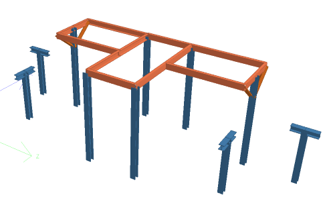
A steel access platform with chequered plate flooring was designed, with beam sizes and support locations optimized within the available clearance and verified per AISC 360, including deflection and vibration checks.
Outcome
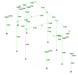
Beam deflection and member utilization ratios were maintained within permissible limits, providing safe maintenance access without loading the piping.
Platform & Pipe Support Inside Valve Pit — 3D STAAD Model View
Results
-
- ✔ Stable support provided for the valve and pipeline system.
- ✔ RCC walls and base slab (500 mm thick) satisfied shear and bending moment requirements .
- ✔ Settlement controlled to 16 mm against a 25 mm allowable limit .
- ✔ Steel members verified for strength and serviceability, with utilization ratios and deflection within permissible limits.
- ✔ Crack-width checks within allowable limits, ensuring serviceability compliance.
Conclusion
The underground RCC valve pit was designed to safely support the 48″ pipeline, MOV assembly, pipe supports, and associated structural components under the required loading conditions, achieving effective load transfer, structural stability, and controlled settlement while maintaining pipeline alignment.
All elements were verified for strength and serviceability in accordance with ACI 318-19, ACI 350-20, AISC 360-22, and ASCE 7-22 — addressing concentrated equipment loads, limited space, earth pressure, groundwater effects, and structural coordination to deliver an efficient, durable, and reliable structural solution.
👉 Talk to Our Engineering Experts