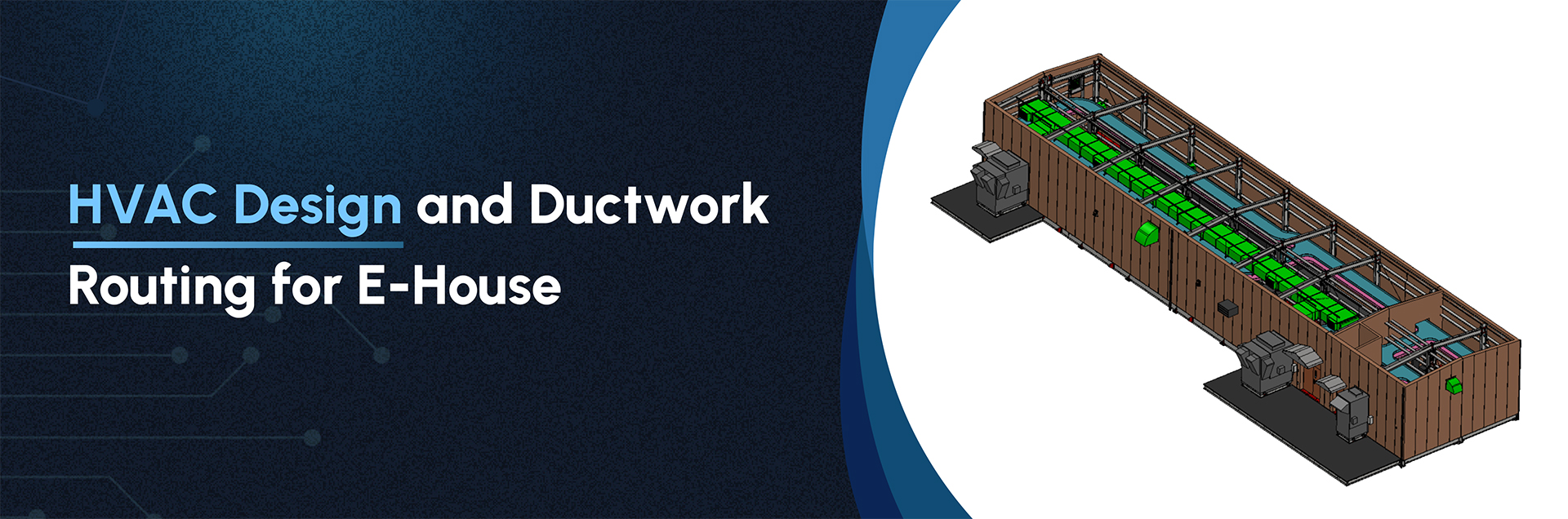
Project Overview
Our team was tasked with designing and routing the HVAC ductwork for an E-house, including creating detailed HVAC layout and elevation drawings. This involved importing the E-house CAD model, modelling HVAC equipment based on vendor prints, and ensuring compliance with industry standards.
Inputs:
- ✔ E-house 3D CAD model with GA drawings.
- ✔ Vendor prints for HVAC equipment.
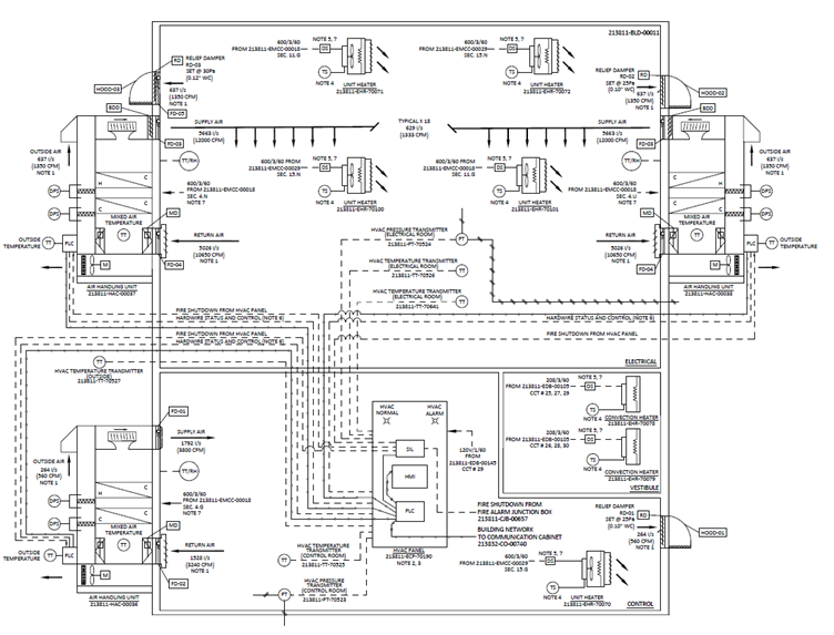
- ✔ Project specifications, including airflow values, sequence of operations, BOM, and control points.
Design Process:
The scope is to design the complete HVAC system involving right from the conceptual layout design to series design and validation through FEA, CFD simulation, 1D Heater core and system level simulation.
- 1. Schematic Creation: Developed schematic and schedule drawings from the project specifications.
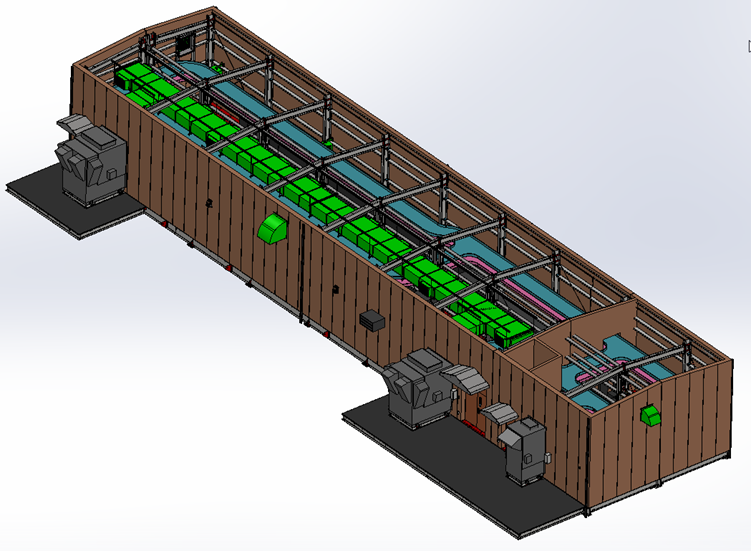
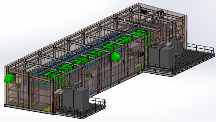
- 2. Modelling and Assembly: Cleaned up and modelled HVAC equipment based on vendor prints. The equipment was assembled inside the E-house as per GA drawings.
- 3. Ductwork Design: Designed and routed the ductwork to avoid interference with other equipment, ensuring compliance with SMACNA and ASHRAE standards.
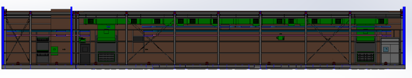
- 4. Layout & Drawings: Created aesthetic 2D layout and elevation drawings, ensuring clear, interference-free representations.
Challenges:
- ✔ The E-house CAD model imported as a single part, requiring careful feature isolation.
- ✔ Ensuring no interference between ductwork and equipment inside the building.
- ✔ Meeting SMACNA and ASHRAE standards for ductwork and support design.
- ✔ Producing clean, overlap-free drawings.
Delivered:
- ✔ 3D models and 2D drawings with detailed equipment layouts and ductwork routing.
- ✔ Control schematic and schedule drawings.
If you would like to know more about this topic.