


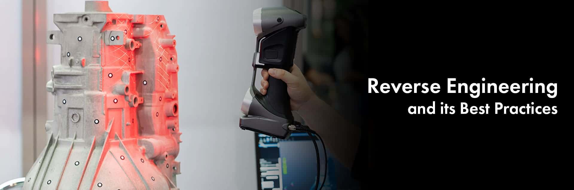
Reverse engineering was originally used only for hard parts, but now this process is applied to software, database and even human DNA.
Reverse engineering is used in performance & feature study of existing product, creating 3D models of the competitor product to analyze them, analyze OE components and make the required changes to make it work better in the after- market, and also to create 3D model and 2D drawing to help Source these products from far away vendors where drawing is not available.
The CMM (Co-ordinate Measuring Machine) invented in 1956, for validating the geometric dimension of the parts. From there, we have come a long way to having handheld devices not to just capture dimensions but also to have a 3D visualization of the component.
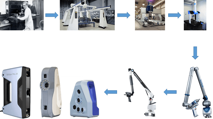
Evloution of Reverse Engineering Devices
Basic reverse engineering steps consist of Probing, Scanning, Surfacing, Extraction of sketches and surface, import surface and sketches, 3D parametric modeling, Comparison of 3D model with the Scan file, 2D drawing generation.
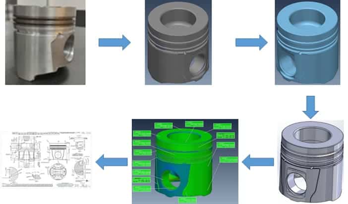
Stages of Reverse Engineering Devices
There are some guidelines to be followed to get the best outcome while Reverse Engineering.
● The component needs to be fixed in a manner where it will not be able to move, otherwise it will result in incorrect scanned data
● White powder is sprayed if component is glossy to avoid reflections
● While scanning, the device should have a laminar flow, this helps in capturing the part more effectively with minimum gaps and noises.
● Optimum distance to be maintained between the scanner and the component to capture the scan more efficiently.
● The scanned data must be aligned to 0,0,0 ordinates, as this will be very helpful while creating parametric model in the end software like Solidworks, Catia or Creo
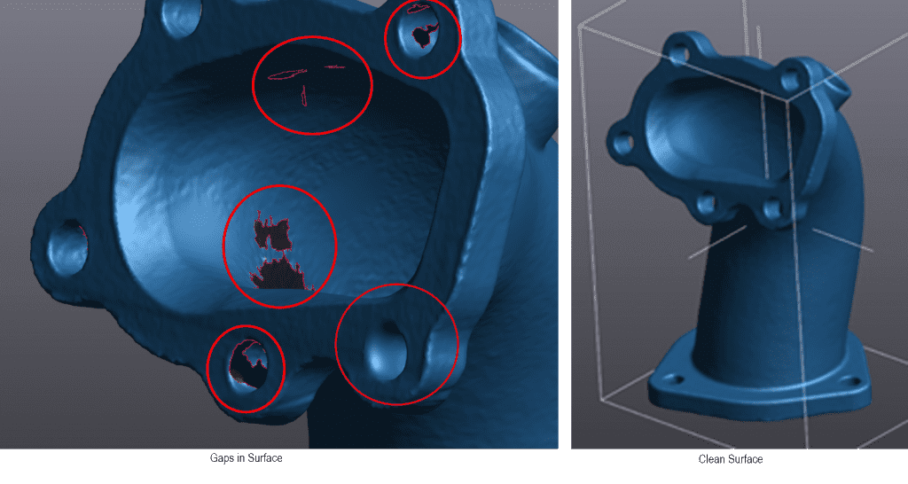
● While generating the surface, ensure all holes are filled and delete the noises. See image below for reference.
● After the surface is ready, take as many cross-sections as possible to generate the sketches. More cross-sections, smoother the transitions between the profiles.
● To ensure the 3D model derived from the scanned data is error free, a comparison is done between the scan data and parametric model and a report will be generated.
The authors, Naveen and Saravanan drive global strategy for engineering solutions at APA Engineering.
They can be reached at naveen@apaengineering.com and saravanan.r@apaengineering.com
Banner Picture Courtesy - Shutter Stock
If you would like to know more about this topic.