


Project Overview
APA Engineering designed and validated a compact fin-tube condenser for an off-road vehicle HVAC system operating under extreme ambient conditions. The objective was to achieve 10 kW heat rejection within a constrained vehicle envelope while ensuring reliable phase-change performance and minimal pressure drop.
Engineering Challenge
Off-highway HVAC systems must operate in harsh environments with high ambient temperatures, dust exposure, and space limitations.
Key Constraints:
- ● High Ambient Condition: Inlet air at 318 K (45°C) DBT — significantly reducing the log mean temperature difference (LMTD) available for heat rejection and demanding higher secondary surface area
- ● Compact Envelope: Hard packaging limit of 520 × 305 × 95 mm — no oversizing margin; coil depth, fin density, and tube count must be optimised simultaneously
- ● Refrigerant Inlet Condition: R134a entering superheated at 370 K / 18 bar (quality 1.1, +37 K above saturation) — requiring the coil to handle desuperheating, condensation, and subcooling zones within a single circuit
- ● Performance Requirement: Complete condensation with a minimum 8 K subcooling margin at the outlet — preventing flash gas formation at the TXV inlet under all operating conditions
- ● Pressure Drop Constraint: Air-side ΔP must remain within blower operating limits; refrigerant-side ΔP must not shift condensing pressure outside the compressor’s design envelope
Engineering Approach
A structured, simulation-driven design workflow was implemented using CoilDesigner®, enabling tube-by-tube resolution of refrigerant phase change, air-side convection, and pressure distributions simultaneously — bypassing the limitations of zone-based or ε-NTU methods.
- ● Requirements Definition: Design boundary conditions locked — 10 kW heat rejection, 318 K ambient, 2,500 m³/hr airflow (actual), 190 kg/hr R134a mass flow rate, 520 × 305 × 95 mm envelope
- ● Geometry Selection: Wavy Herringbone fin surface selected for its superior convective enhancement at moderate face velocities (4.38 m/s); 19 FPI chosen to maximise secondary area (24.19 m²) while controlling air-side pressure drop within blower capacity
- ● Detailed Simulation: Full tube-by-tube CoilDesigner® model executed — resolving refrigerant enthalpy, quality, pressure, and temperature at each segment; air-side convective coefficient and pressure drop computed simultaneously using Wavy Herringbone correlation
- ● Design Validation: Final configuration confirmed against all targets — 10 kW heat rejection, 8 K subcooling, 0.005 bar air-side ΔP, 0.035 bar refrigerant-side ΔP, and outlet quality of −0.081
- ● Deliverables: CoilDesigner® simulation file (.chx), full state-point results report, coil geometry specification sheet, and off-design performance maps issued for procurement and prototype fabrication
COIL DESIGN SPECIFICATIONS
| Parameter | Value |
|---|---|
| Configuration | 12 Rows × 6 Columns |
| Total Tubes | 72 |
| Tube Length | 520 mm |
| Row / Column Spacing | 25.4 mm / 15.88 mm |
| Fin Type | Wavy Herringbone |
| Fin Density | 19 FPI (Fin Pitch: 1.34 mm) |
| HX Height × Width × Depth | 304.8 × 520 × 95.28 mm |
| Face Area | 0.158 m² |
| Total Heat Transfer Area | 25.19 m² |
Thermal Performance
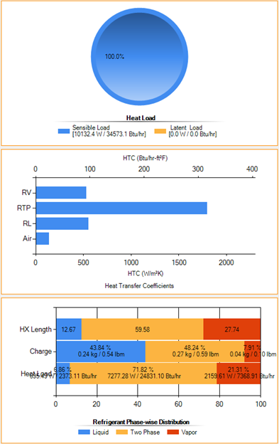
- ● Total Heat Rejection: 10 kW (fully sensible — SHR = 1.0, zero latent load)
- ● Air Mass Flow Rate: 2,778 kg/hr | Actual Volumetric Flow: 2,500 m³/hr
- ● Refrigerant Mass Flow Rate: 190 kg/hr (R134a)
- ● Average Air Face Velocity: 4.38 m/s
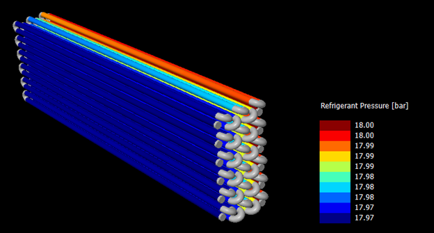
- ● Refrigerant-Side Pressure Drop: 0.035 bar
State-Point Summary
| Parameter | Inlet | Outlet |
|---|---|---|
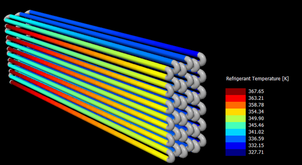
| Temperature | 370 K (97°C) | 323 K (50°C) |
| Pressure | 18 bar | 15.96 bar |
| Refrigerant State | Superheated vapour | Subcooled liquid |
| Quality | 1.1 | -0.081 |
| Saturation Delta | +37 K (superheat) | -8 K (subcooling) |
The condenser achieves complete phase transition across three distinct zones — desuperheating, condensation, and subcooling — within a single coil circuit. The 8 K subcooling margin at the outlet ensures single-phase liquid refrigerant reaches the expansion device under all operating conditions, eliminating flash gas losses and protecting TXV metering accuracy.
- ● Achieved 10 kW heat rejection at 45°C ambient (318 K) dry-bulb with R134a at 190 kg/hr mass flow rate — confirming full design capacity under worst-case off-road thermal loading
- ● Achieved 8 K subcooling margin (refrigerant outlet quality −0.081) at 15.96 bar condensing pressure — eliminating flash gas formation at the TXV inlet and ensuring stable compressor suction conditions across variable load cycles
- ● Delivered a packaging-compliant coil within the 520 × 305 × 95 mm vehicle envelope — 12-row × 6-column, 72-tube configuration with 0.158 m² face area and 24.19 m² total secondary surface
- ● Optimized refrigerant circuiting via tube-by-tube CoilDesigner® simulation — limiting refrigerant-side ΔP to 0.035 bar while maintaining uniform flow distribution across all 72 tubes, avoiding maldistribution-induced capacity loss
- ● Delivered simulation-validated, manufacturing-ready outputs — CoilDesigner® result file, full state-point data, geometry specification sheet, and off-design performance map ready for RFQ and prototype fabrication
Conclusion
This project demonstrates APA Engineering’s capability to deliver high-performance, space-efficient condenser designs for demanding off-road applications using advanced simulation tools like CoilDesigner®.
👉 Talk to Our Thermal Engineering Experts